...Return To Mine & Other Bonneville Car Construction Pages
.Previous Page...............B'ville Car Index Page.........................Next Page
..............................-- Mount for Left Front Axle --
................... .
.
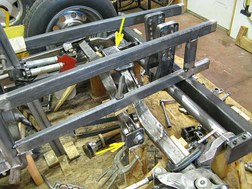
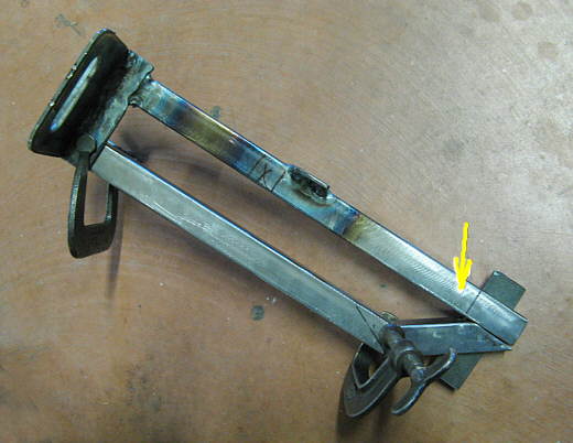
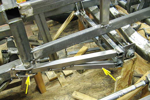
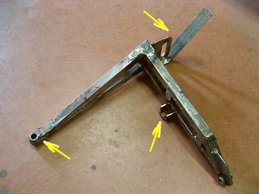
On the last page the mount to locate the right axle was completed (top arrow). Now the mount for the left axle will be made to locate the right end of it (bottom arrow). The mounts are different since the locations are different. This one will be easier since it is in a more open area. The slotted adjustment piece had already been made and is on the end of the heim joint and in location (bottom arrow). I moved it up and down and with the wheel/tire on got the camber set to zero with the hemi in the middle of the slot travel.
................... .
.
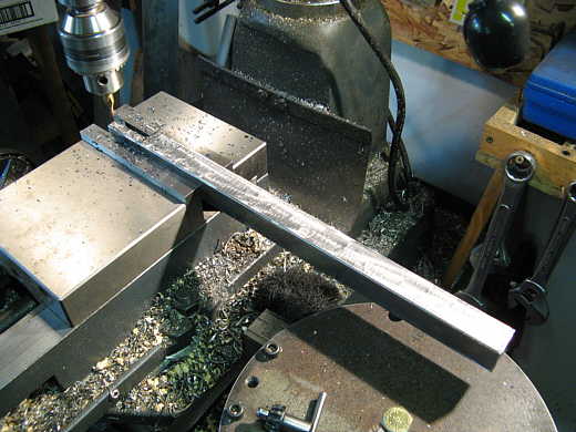
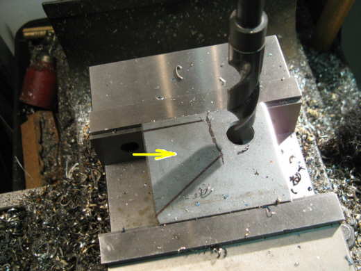
This piece is being slotted to 3/16 of an inch so a bracket can be slid into the slot and welded to the 1 inch square tubing.
................... .
.
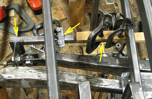
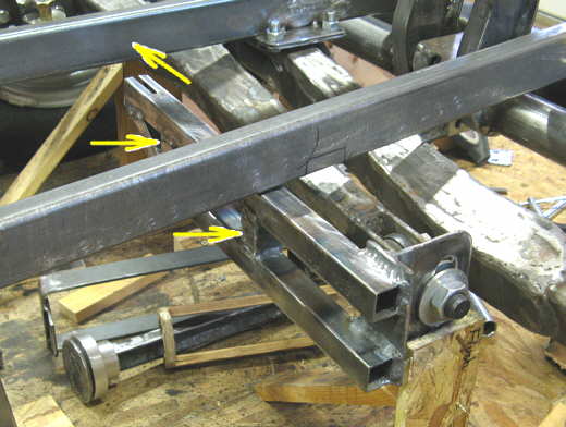
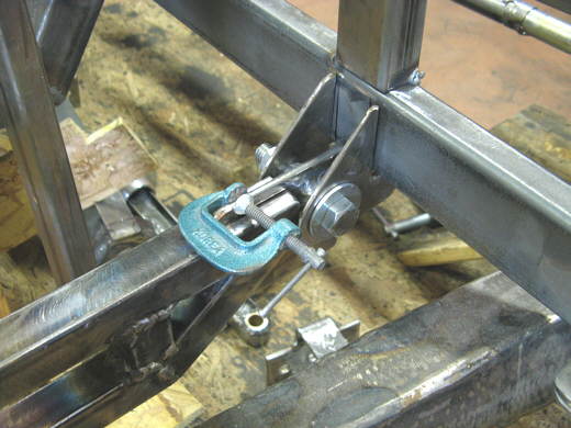
Here a piece of strap has been welded to the piece with the slot in it (left
arrow) and the square tubing from the last picture was tacked to the vertical piece of strap (left arrow). The
square tubing goes over near the frame member by the c-clamps. A tab was welded to the square tubing (middle arrow)
and another tab was bolted to that tab and tacked to the frame member on the left side (middle arrow).
...................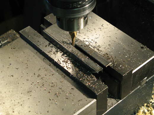
A short piece of tubing was also slotted and ........................
...................
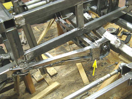
.......... it was added underneath the first piece at an angle (arrow). While this was being welded a piece of strap was temporarily put into the slots to align the pieces. A second bottom member was also tacked into position.
...................
The top arrow points the where this assembly will be attached to the frame member once I add a piece into the slot. The other arrows point to vertical members that make the assemble more like a truss.
................... .
.
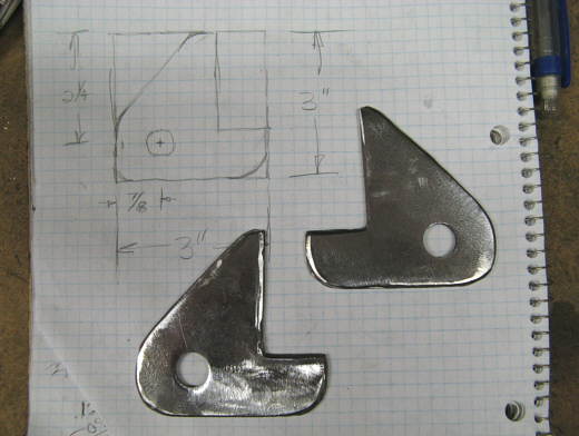
This is the piece that will go into the slot on the end of the assembly. the arrow points to the marked off area that represents the outline of the square tubing. I drilled a 3/4 inch hole in the 3/16 inch thick strap.
....................... .
.
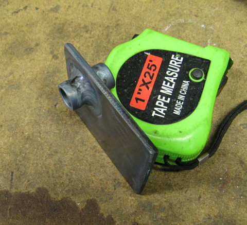
A bushing with a 3/4 O.D. and a 1/2 I.D. was made on the lathe and tig welded into place.
................... .
.
These are the frame brackets that were made to go on the frame member and locate the end of the assemble that is being made.
................... .
.
The frame brackets are in position along with the strap with the bushing that has been placed in the slotted assembly All of this can now be tacked in place. This concludes locating the axle end locator assembly up and down and side to side in the car. Now I have to locate the end of the axle fore and aft in the car.
................... .
.
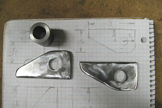
The 1 inch O.D. bushing with a 5/8 inch I.D. was again made with the lathe and these two brackets were made.
................... .
.
The brackets attach to the frame rails (left arrow) and the bushing was placed between them. Another piece of 1 inch square tubing was then welded to the bushing and over to the previously made assembly. Another piece of square tubing was welded in at an angle (right arrow). Next everything to this point was welded together.
................... .
.
Then reinforcing straps were put into place. The left arrow points to a piece of strap that wraps around the bushing and is welded to the sides of the square tubing. The bottom right arrow points to gussets at are being welded onto the tabs. They will be then ground round on the outside. The top arrow points to a piece of strap that is being wrapped around the slotted piece and tied into the main assembly.
................... .
.
The arrow points to another gusset that ties the whole end of the assembly together.
................... .
.
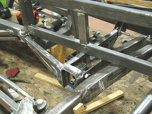
The completed assembly in place. All that remains is to gusset and finish weld the frame brackets. I feel good about getting the axle ends finally located. The front is coming together.
..............................................................Next Page